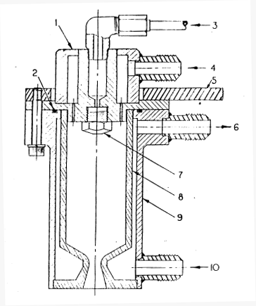
Figure 8 Assembly drawing of small liquid-fuel rocket engine. (1) injector assembly, (2) O-ring, (3) liquid fuel, (4) gaseous oxygen (5) engine mount, (6) coolant, (7) fuel spray nozzle, (8) combustion chamber, (9) outer shell, (10) coolant.
The fabrication and assembly of a small liquid fuel rocket engine is no more difficult than the more serious amateur machine projects, such as model steam engines, gasoline engines, and turbines. Because the rocket engine has no rotating parts, dynamic balance of components is not required. However, the use of quality, homogeneous materials and careful fabrication technique are definitely required to produce a safe, working rocket engine.
A properly desgined small liquid-fuel rocket engine requires the following machine and hand tools:
Since a properly designed engine will have symmetrical parts, a milling machine or planer will not be required. The metal-turning lathe should have a repeatable accuracy of 0.001 inch. The drill press will he used to drill small diameter holes and should have a true running, high speed chuck.
Mensuration equipment such as calipers, micrometers, etc., must be capable of inside and outside diameter measurements, lengths, and should be used to locate holes, recesses, and other features prior to actual machining.
The joining of the various engine components is especially critical since the engine will operate at high pressure and high temperature.
Figure 8 Assembly drawing of small liquid-fuel rocket
engine. (1) injector assembly, (2) O-ring, (3) liquid fuel, (4)
gaseous oxygen (5) engine mount, (6) coolant, (7) fuel spray nozzle,
(8) combustion chamber, (9) outer shell, (10) coolant.
The ability of the welder, and the welding techniques employed, should be as good as those required for aircraft work. Metal joints must be clean, vith a close fit between parts to ensure adequate weld strength and integrity. To the extent possible assembled conponents should be tested with water (or nitrogen gas, but that is dangerous) prior to actual use with propellants. Repair of leaks or initially poor welds must be carefully done with subsequent re-testing with pressurized water (called hyrdo-testing or hydrostatic testing).
As discussed previously, the combustion chamber should built as a one-piece unit. This arrangement, while more difficult from a machining point of view, eliminates the requirement for a joint of some knd between the two parts; this joint would be exposed to the hot combustion gases (5700 degF) on one side and would, in all probability, fail. Building the combustion chamber and nozzle in one piece eliminates this potential failure point. Care must be exercised during the machining of the copper chamber/nozzle to ensure constant wall thickness and the correct taper in the nozzle region. Thin wall sections are potential failure points and could result in almost immediate catastrophic failure during firing.
Machining of the outer shell or jacket is less critical than the combustion chamber/nozzle. Typical materials for this part are stainless steel or brass. The inside diameter of the shell should have a smooth finish to reduce cooling pressure drop, nnd the outside finish of the shell, which will be visible to the world, should reflect the care and concern of the machinist. The shell will also contain the coolant entry and exit ports. Since the coolant (typically water) will probably have an entry pressure of 60 to 100 psi, these ports and fittings should be constructed with some care. The use of flare type fittings with metal tapered seats (such as those manufactured by Parker or Weatherland) is highly reccomended. The shell will also feature a method of attaching the injector and for mounting the engine to a test or thrust stand. As shown in Figure 8, these two mounting requirements can be easily combined to simplify the design. The forces to be considered when designing the shell are not the thrust forces (which are small, typically on the order of 20-30 lbs) but, rather the pressure forces attempting to separate the injector from the shell. The pressure acting on the injector area out to the point of sealing between the injector and the outer shell is the combistion chamber pressure, which is typically 100 to 300 psi. The force attempting to separate the injector from the shell is slightly over 600 lbs for the design shown in Figure 8 at a combustion pressure of 300 psi. The bolts holding the two components together (and in this case also holding the assembly to the test mount) must withstand this force with and adequate safety factor (typically a factor of two). THe number and size of bolts required can be obtained from Table IV, which gives the average load capacity of high strength steel bolts of various sizes. The strength of these bolts, however, depends to some extent on the adequacy of the threads in tapped holes, the tapped material, and the bolt tightening procedure used in assembly.
Bolt Size | Load Capacity, lb

10-32		1500
1/4-20		2400
1/4-28		2750
3/8-16		5800
The outer shell must also contain a sealing device to prevent the high pressure combustion chamber gas from flowing back past the injector. With an appropriately configured water-cooled design, the use of an elastomeric O-ring is highly desirable. A standard neoprene O-ring (manufactured by a number of companies, see List of Suppliers) will give reliable service if the surrounding metal does not exceed a temperature of 200-300 degF . Dimenstions and design parameters for O-rings and O-ring grooves are given in maufacturers supply catalogs.
Another method of sealing is the use of an asbestos-copper crush gasket (very similar to those used on automobile sparkplugs, only larger; see List of Suppliers). The copper crush gasket is positioned by a V-groove cut in the surface of the outer jacket at the sealing point. The mating surface of the injector should be smooth and flat with no machine marks.
Figure 9 illustrates the relationship between an O-ring and a copper crush gasket and their mating surfaces.
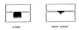
Figure 9 Detail on O-ring and crush gasket sealing
methods. O-ring groove dimensions are critical and should be obtained
from suppliers handbooks. Crush gasket groove dimensions are
non-critical; groove depth should be about 1/3 the thickness of
uncrushed gasket.
The injector should be fabricated from copper to provide maximum heat transfer from the injector face to the incoming propellants. The outer shell of the injector can be made from either copper, stainless steel, or brass. However, since the propellant inlet fittings (again these should be the tapered seat, metal-to-metal kind) should he stainless steel for best results. It is usually a good idea to make the injector outer shell from stainless steel so that the inlet fittings can be arc welded. Then the outer shell can be attached to the remainder of the injector by silver brazing without weakening the inlet fitting welds.
Injection holes for the gaseous oxygen (and for the fuel, if impinging jets are used) will usually be made with numbered drills of small diameter. Extreme care should be used in drilling these holes, especially in soft copper. The drilled hole should have an entry and exit free from burrs or chips. It is vitally important that injector components be thoroughly cleaned and deburred prior to assembly. After injector welding, hot water should be used to thoroughly clean the injector assembly of brazing flux and residues, and the assembly should receive a final rinse in acetone or alcohol.